Category: Elect. & Comm.
 Living in this technological world, where machines have been an
integral part of human life not only just bringing an ease to his workout but an upswing to his
spurtness.
But the thing to be noticed is that all these advancements are targeted to just give an upsurge
to our pre luxurious life.
But the recent advancement in biological and technological merge have given birth to such
technologies which not only aim towards the future boom but also towards the things focusing
a better life for the disables, and the recent example in this field is the brainwave
technology.
To download the complete abstract :

RELATED POSTS:
VARIABLE REGULATED POWER SUPPLY–PROJECT
________________________________________________________________________________________________
A combined project by Abhishek, amit and me.
Following is the list of parts or the components required to design this project:
- IR receiver module TSOP1738
- Transistor T1 (BC558)
- Decade counter IC CD4017 (IC1)
- LED1 (red)
- LED2 (green)
- Transistor T2 (BC548)
- Relay RL1, 5V, 100 ohm
- Diode 1N4007 (D1)
- R1 = 220K
- Bulb Holder
- Bulb
- R2 = 330 ohm
- R3 = 1K
- R4 = 330 ohm
- C1=100 uf,16V
- C2=0.1 uf
- 5V dc supply
- Soldering Iron ,Solder wire
- PCB Designing Material
- 2 Pin plug
- Wires
Connect this circuit to any of your home appliances (lamp,fan, radio, etc) to make the appliance turn on/off from a TV, VCD or DVD remote control. The circuit can be activated from up to 10 metres.The 38kHz infrared (IR) rays generated by the remote control are received by IR receiver module TSOP1738 of the circuit.
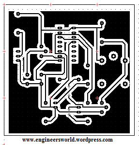
PCB LAYOUT :
CIRCUIT DIAGRAM:
AFTER COMPLETION:
WORKING PROJECT:
____________________________________________________________________________
To provide this project a small area here i am giving a small PCB layout of the above design:
Its a new simplified form of PCB layout of above project.
Well you all guys have seen the movie Robot by Mr. Rajnikant , and have noticed the technology he uses in movie for the wireless data transfer i.e. zigbee ,so lets have a look What this Zigbee is?
ZigBee is a new low-power wireless communications technology for wireless networks looking for lower cost, limited functionality, reduced data size, and protocol simplification.
Applications:
1.mobile handsets
2.local area networks
3.wide area networks
4.pc and tabs
5.high tech electronics
6.portable devices
Softwares required:
1.Bee stack
2.SMAC
Soon zigbee will replace the positions of bluetooth in your pc’s and cells.
Well technology is imerging with a great upsurge and really these gadgets are the boon for us…
There is always a question in my mind whenever the thing is to choose a mobile network that wheather i take the gsm or the cdma?
But the real question is what the difference is,which one is prior??
So i just wanna enlighten some common but unnoticeable points regarding both by this article:
1.CDMA is much secured as compared to GSM as it uses code multeplexing.
2.CDMA sets uses much power than the gsm sets and this got a increase when we leave the home region,and it is due to the same code multeplexing.
3.GSm can be tapped but not the CDMA.
4.By the use of JAMMERS gsm networks can be jammed in a locality but it doesnt works on cdma.
5.CDMA is faster than GSM in data transfer,but both services are growing or we should say developing to overleap each other.
6.CDMA uses R-UIM cards which are only compatible to their handsets while in GSM it uses SIM cards thus providing a variedness.
Well all these were just a tech difference between the two , its upon you what you choose….enjoy!!
Related posts:
Program to add two continuous signals in MATLAB
Program for convolution of continuous sequences in MATLAB
_____________________________________________________________________________________________________
Program to draw a circle in MATLAB:
r=2;
t=0:pi/24:2*pi;
x=r*cos(t);
y=r*sin(t);
plot(x,y,x,y,’*’)
grid on
Program for addition of two continuous signals in Matlab:
x=linspace(0,2*pi,100);
a=sin(x);
b=cos(x);
c=a+b;
y=plot(x,a,x,b,’*’,x,c,’+’)
Here is the program for convolution of two continuous sequences in MATLAB:
x=[1 0 -1 1 1];
t1=length(x);
h=[1 1 1 1 1];
t2=length(h);
y=conv(x,h);
t=1:1:t1+t2-1;
plot(t,y)
RELATED POSTS:
1.VHDL Code for 4 bit comparator
3.VHDL code for 2 to 4 binary decoder
______________________________________________________________________________
Here is the VHDL code for FULL ADDER:
LIBRARY ieee ;
USE ieee.std_logic_1164.all ;
ENTITY fulladd IS
PORT ( Cin, x, y : IN STD_LOGIC ;
s, Cout : OUT STD_LOGIC ) ;
END fulladd ;
ARCHITECTURE beh OF fulladd IS
BEGIN
s <= x XOR y XOR Cin ;
Cout <= (x AND y) OR (Cin AND x) OR (Cin AND y) ;
END beh ;
Subscribe us for more such details directly to your mail,and write here for any of your queries and suggestions.
Below is the program of parity checker in 8085 microprocessor which is successfully executed.Here i am checking the parity of number 05.
MVI A,05H (MOVING 05 TO ACCUMULATOR)
MVI B,08H (THERE IS 8 BIT NUMBER SO INITIALIZING B TO 08)
MVI C,00H (INITIALIZING COUNTER TO 00)
STC (SETTING THE CARRY)
CMC (COMPLIMENT OF CARRY ,SO CARRY BECOMES ZERO)
LOOP::RAR (HERE LOOP BEGINS,NOTE THE ADDRESS OF THIS REGISTER TO BE USED FURTHER)
JNC level 1:: (WRITE THE ADDRESS OF LEVEL 1)
INR C (INCREMENT IN C)
level 1::DCR B (DECREMENT IN B)
JNZ LOOP:: (HERE SPECIFY THE LOOP ADDRESS)
HLT
So that’s the program for parity checker, subscribe us on your mail directly for more such programs and information related to 8085 microprocessors.
Please mention your views and comments over the post and the blog.thank you.


